

Table of Contents
- Watch What the Operator Does During Loading
- A Fixture That Opens and Closes Automatically May Still Need Changes
- A Hydraulic Fixture May Also Need Its Own Power Unit
- “The Robot Is Very Repeatable. Why Would the Part Not Fit?”
- Where Compensation Can Help
- A Short Note on Automatic Doors
- Will There Be Enough Space Around the Machines?
- Training During FAT Gives the Team an Earlier Start
- The Small Components That Can Wait in a Busy Toolroom
- What Should Your Team Prepare Before Delivery?
In this article:
- Why the system demonstrated at an exhibition may not represent a complete production cell.
- Which overlooked manual steps must also be automated for reliable robotic loading and unloading.
- Why robot repeatability alone does not guarantee that a close-fitting part will load reliably.
- How machine preparation, layout and FAT can affect both project scope and on-site start-up.
In my conversations with manufacturers about robot investments, exhibition prices sometimes come up. Someone has seen a demonstration, asked about the price and started considering a similar investment for their own factory. Others have spoken to a nearby manufacturer who recently installed a robot.
That gives us a useful starting point. As we discuss the manufacturer’s own machines, parts and production process, however, the project may begin to include preparations that were not visible in the original demonstration.
Why does automating our machine require more investment than the system we saw at the exhibition?
That is what I would like to explore through a few examples we regularly encounter at Robsen.
At exhibitions, we often see a robot demonstrating a loading and unloading sequence without an actual machining centre. It picks up a part from a conveyor or fixture, moves it to a demonstration position and returns to collect another. We can see the robot’s movement and capabilities, but we are not necessarily seeing a complete production process.
In your factory, the robot must work with your machines, fixtures and parts. Some may already be suitable for automatic loading. Others may need preparation.
What the Exhibition Shows—and What the Factory Project Must Resolve
Exhibition demonstration | Factory project |
|---|---|
Robot, gripper and repeatable movement | Actual part pickup, orientation, loading, release and unloading |
A demonstration stand or simplified fixture | Production fixtures, locating tolerances and clamping behaviour |
An open demonstration area | Setup, cleaning, maintenance and chip-conveyor access |
A standalone demonstration cycle | Machine communication, door operation, utilities and operator training |
When we develop a project at Robsen, we examine these details together with the customer. We discuss how the fixture will operate, how the machine will communicate with the robot and what needs to be manufactured or modified before installation. From there, we can agree on which work belongs to us, which preparations the customer will undertake and where specialist support may be helpful.
The exhibition price belongs to the demonstration you saw. Your investment belongs to the production process you need to automate.
Watch What the Operator Does During Loading
One of the most useful things we can do during a factory visit is watch the loading operation closely.
In some applications, the operator places the workpiece over locating pins, adjusts its angle and presses it into position. They may use a soft-faced mallet to help it sit fully against the fixture before tightening the clamps.
After machining, opening the clamps does not always leave the part free to lift away. In some operations, the operator needs to pull firmly to release it from the pins. In others, they use a lever to help loosen it.
When we describe this simply as “manual loading and unloading,” it is easy to overlook how much the operation depends on the operator’s sense of touch and ability to control force.
Our hands having their own natural force/torque sensors. We feel which side of a part is catching, whether it needs a slight turn and how much pressure to apply. We can ease off, change direction and try again almost without thinking.
A robot following a programmed movement does not automatically have the same feedback. If a part catches on a pin and the robot continues moving, the resulting force can put the robot wrist and axes, the fixture and the gripper at risk.
This is why I like to ask a few practical questions while watching the operation:
- Why does the operator need to tap the part?
- Where does it catch?
- Why does it sometimes require a strong pull to come out?
The answers help us identify what needs to change so the robot can load and unload the part consistently.
The robot does not need to imitate the operator’s hands. The process must be prepared so that it no longer depends on the small corrections those hands make.
A Fixture That Opens and Closes Automatically May Still Need Changes
Many manufacturers use manual fixtures. The operator places the part, positions it and tightens the clamps with an Allen key. Other applications already use fixtures with pneumatic or hydraulic clamps.
An automatically operated fixture gives us a useful starting point. Before using it with a robot, however, there is an important detail to examine: what happens to the part while the fixture closes?
Suppose the robot brings a workpiece into the fixture. Because of the part’s geometry, it continues holding the workpiece while sending the signal to close the clamps.
As the fixture closes, it centres the part. In doing so, it may move the part slightly sideways or pull it down against a locating surface. The robot, meanwhile, is still trying to hold the part in the position where it was programmed to stop.
Without a suitable arrangement to accommodate that movement, the fixture’s clamping force can travel through the workpiece into the robot wrist and axes. Depending on the forces involved, this can damage the robot, gripper or fixture.
In our applications, we try to create an arrangement in which the robot can place the part securely in the fixture, release it and move clear before clamping begins. The fixture can then locate and clamp the workpiece without the robot continuing to hold it.
That may require a support, a locating feature or a change to the fixture jaws. Sometimes the geometry calls for a different approach, which we work through with the customer and the fixture designer.
This is the distinction I want to highlight: a fixture can open and close automatically yet still require design work before it is suitable for reliable robotic loading.
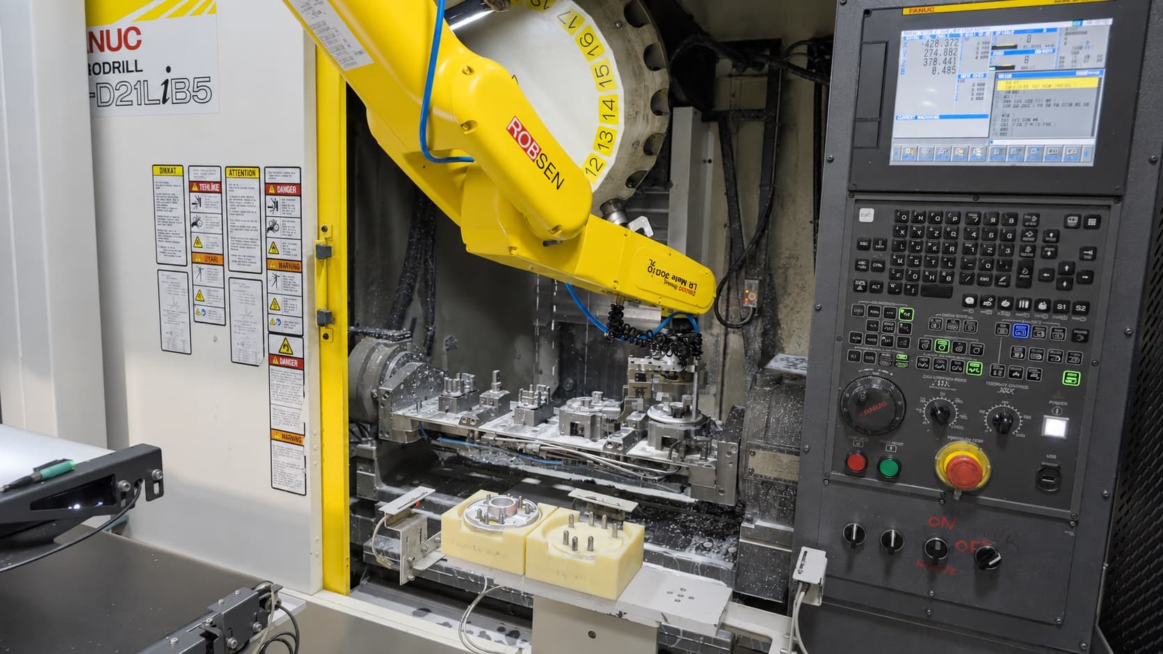
An IROCUBE machine-tending system loading a FANUC ROBODRILL equipped with automatically operated fixtures. Automating the clamps is only part of the work; the complete locating, clamping and release sequence must also support reliable robotic handling.
A Hydraulic Fixture May Also Need Its Own Power Unit
Another item that can appear in the preparation budget is a hydraulic power unit.
I understand why this is sometimes unexpected. You look at the machine, see an existing hydraulic unit and think, “We already have one.”
If the machine does not currently have hydraulic workholding, that unit may be serving functions such as tool clamping or tool changing. The new fixture may require a separate hydraulic supply, so an additional power unit and its connections can become part of the installation.
This is worth discussing with the machine supplier and fixture specialist early. Then, when the fixture quotation arrives, the supporting equipment has already been considered.
“The Robot Is Very Repeatable. Why Would the Part Not Fit?”
A similar discussion arises when a part needs to be placed onto locating pins at an inspection, marking or intermediate station.
A close fit can be quite manageable for a person. Our natural sense of touch helps us feel the contact and make tiny adjustments until the part slides into place. The same fit can be more demanding for a robot following a fixed approach.
At that point, a reasonable question is: “The robot has very good repeatability. Shouldn’t it be able to do this?”
For example, FANUC specifies a repeatability of ±0.02 mm and a maximum wrist payload of 12 kg for its M-10iD/12. But robot repeatability is only one of the variables involved in placing a part. See the official FANUC M-10iD/12 specifications.
Consider a workpiece with two holes that must fit over two pins. The holes have manufacturing tolerances in both size and position. The pins have their own manufacturing and positioning tolerances. The gripper fingers also have tolerances, and the workpiece may sit slightly differently between them each time it is picked up.
All these variations meet when the robot brings the holes towards the pins. Looking only at the robot’s repeatability therefore gives us an incomplete picture of how reliably the part will fit.
Robot repeatability does not cancel the tolerances of the part, gripper, pins and fixture.
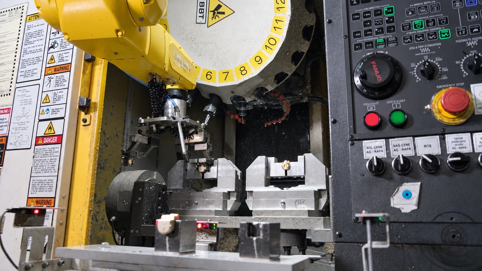
The robot, gripper and automatic fixtures work as one positioning system. Robot repeatability must therefore be evaluated together with the tolerances of every component in that chain.
One approach is to make the initial entry more forgiving. A pin with a tapered tip, for example, can guide the hole into position instead of requiring it to align immediately with the full diameter of a cylindrical pin.
These can be relatively small design changes, but they deserve attention while the process is being prepared.
Where Compensation Can Help
Compensation units are another option. They allow a defined amount of movement between the robot and gripper, helping the assembly accommodate small misalignments.
They also have a purchase cost and add weight at the robot wrist. On a small robot already carrying two grippers and two parts, adding compensation equipment can bring the total load closer to the robot’s payload limit.
We therefore evaluate compensation together with the complete gripper assembly. In some applications, it is a useful addition. In others, improving the fixture’s loading arrangement may be the more appropriate solution.
Force/torque sensing can also support controlled insertion where the application requires it, with additional equipment and integration work included in the project scope.
A Short Note on Automatic Doors
If the machine door is operated manually, we also need to decide how it will open and close during the automatic cycle. A dedicated automatic-door mechanism can help shorten the time the machine waits during a part exchange.
Depending on the project, this work may be carried out by the integrator, the machine supplier or a team specialising in automatic-door systems. It is another preparation item worth including in the plan from the beginning.
Will There Be Enough Space Around the Machines?
During a layout discussion, we may look at two machines currently served by one operator and consider placing the robot between them.
It is an understandable starting point, but there are several details I like to check before settling on that position.
The robot needs room to move its arm, gripper and workpiece through the complete loading path. The machines also need access for setup, cleaning and maintenance, including occasions when an operator must intervene while the robotic cell is safely stopped.
A chip conveyor can make this especially clear. Where it projects into the space in front of the machine, an operator can step away when access is required. A robot fixed to the floor continues to occupy that position.
An offset mounting position or an overhead arrangement may help, depending on the application. A linear rail can provide movement flexibility in some layouts, although the rail and its supporting structure must still be considered when checking service access.
We may also discuss whether the machines could be positioned farther apart. That conversation naturally involves the customer’s production team because moving a machine can require utility work, levelling and time away from production.
These details are difficult to judge from a robot demonstration. They become clearer when we study the proposed installation in the actual factory.
Training During FAT Gives the Team an Earlier Start
At Robsen, we include training during the FAT—Factory Acceptance Test—while the system is still at our facility.
This gives the customer’s team time with the equipment before it arrives at their factory. They can follow the sequence, ask about situations they expect to encounter and become familiar with the system alongside our team.
Operators, maintenance staff and engineers naturally look at the system from different perspectives. Operators want to understand daily use and recovery. Maintenance staff need to know what to inspect and maintain. Engineers may be considering future parts, new gripper fingers or changes to machine fixtures.
It is not always easy to release these people from daily production, and attendance can sometimes be limited. But making time for FAT and training gives them an earlier start, before installation brings the pressure of getting production underway.
For customers planning further robot investments, that knowledge also helps with the preparation of the next project.
The Small Components That Can Wait in a Busy Toolroom
There is one preparation issue I have noticed in factories with very capable toolrooms.
Their teams produce large forging dies, die-casting dies or injection moulds. The work involves considerable engineering and craftsmanship, often supported by decades of experience.
Then a robot project needs a small gripper finger, locating bracket or 100 × 100 mm plate.
That small component must find a place in a workshop whose machines and schedule are organised around much larger jobs. It can be left waiting for an available gap, even though the robot project may be waiting for it.
I remember a customer who recognised this while still at an early stage of robot investment. They wanted to establish a dedicated robot-fixture workshop, with smaller machines and a focused team working on gripper fingers, machine fixtures and intermediate locating equipment.
I thought that was a particularly thoughtful decision. Before installing many robots, they were already considering how their own team would support the preparation work.
A separate workshop will not suit every factory. But giving these jobs a clear place in the schedule, with a small team that understands their importance, can help considerably.
What Should Your Team Prepare Before Delivery?
The lowest number on a quotation does not always represent the complete investment, and a higher number does not necessarily mean that the integrator is supplying the same system at a higher margin. The difference may be in the fixture modifications, machine interfaces, door automation, utilities, layout work, testing and training required to make the cell perform reliably in your factory.
Before comparing robot proposals, ask each integrator to define three things clearly:
- What is included in the robotic cell?
- What must be prepared on the machine and fixture?
- Which responsibilities remain with the customer or another supplier?
For a project with a 16-week delivery period, for example, we can explain which fixture, machine, layout and training activities the customer’s team can complete during those weeks.
That gives both sides time to prepare the installation together, so the robot arrives at a factory that is ready to put it to work.
If you are evaluating a machine-tending investment, Robsen can review the application with your team and help define these preparation responsibilities before the project begins.